Having fun with Arduino
Tagged with: [ arduino ] [ C ] [ electronics ]
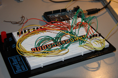
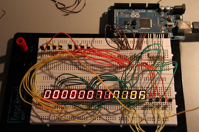
So yesterday I’ve finally received my Arduino Mega. If you know me, you know I’m not even capable (or allowed) to handle a screwdriver, let alone something even more complicated things like transistors, resistors etc.. However, with the help of some friends over on the #pfz channel on freenode to create the schematics, I’ve made - and programmed - a very simple lcd-counter consisting of 3 times a 4-digit 7-segment lcd’s.
The schematics
First, we need an arduino. It a microprocessor with lots of input and output pins we can control. Next, we need 3x 4-digit 7-segment lcd’s. Normally, you would think that controlling something like that would mean we need 7 pins per digit, so 28 pins for each lcd, but it’s actually a bit more clever than that. We still need 7 pins to control the segments, and we have 4 additional lines to control which digit in the lcd we are actually working with.
So if we put power 7 segment pins AND we put power on the LCD-1 pin, we get a nice ‘8’ on the first digit, but not on the other 3. If we change the LCD-1 pin into the LCD-3 pin, digit 3 will light up (and off course, digit 1 will be off again). If you do this for all digits in a fast enough tempo, you create the “illusion” that all digits are on at the same time (more or less the same trick is used by your OS, to switch between multiple processes).
Now, apparantely, because of some mysterious electronica-rule I never really mastered, we need to place resistors between our lcd’s and arduino pinouts. Otherwise the galaxy explodes, so I’ve heard. Again, #pfz told me that I need 100 ohm resistors so i’ve installed those between the pinouts and the lcd’s.
Here is where things gets a bit difficult: we have 2 different kind of outputs, 7 outputs (8 if you count the separate ‘dot’ on the lcd we can control) are our segment lines. We connect them directly to the arduino with the help of the resistors. The which pin we need to connect (there are 16 on the lcd) can be found in the datasheet which tells us that pin 14 controls the ‘A’-segment, pin 16 the ‘B’-segment etc. I don’t know where they aren’t sequential, since connecting the lcds now creates a bit of a mess on my board.
To connect the other leds, we simply connect pin 16 of lcd1 to pin 16 of lcd2 and pin 16 of lcd3. In theory, we could add a whole lot of lcd’s behind eachother but I guess there are some other electronic stuff I don’t know about that would forbid that. Anyway, linking 3 of them works without problem for the time being.
Now we have to connect the “digit” pins, the pins that controls which digit on the lcd is active. As said, there are 4 digits per lcd, and i’ve got 3 of them so a total of 12 pins are needed to connect them all. Unfortunally, we cannot connect them directly to the arduino as we did with our segment-lines. Instead, we add transistors.
Now, transistors are somewhat like microswitches with 3 ports. port 1 holds the input, port 3 holds the output and port 2 decides wether or not the switch is clicked or not. If there is no power on port 2, there will be no current flowing from port 1 to port 3. This makes it possible to have a small voltage control the flow of a larger voltage flow. We need a bit larger voltage for getting the lcd’s up and running, so we let the arduino only control the transistors.
The actual power for the lcd’s come from a secondary line, which - to make things even more confusing - is on the arduino board as well. There is a separate 3.3v and 5v pin you can use to power whatever you want.
Now that we have connected our lines, lcd’s, resistors and transistors, we have something that actually can function.
I’ve build my setup on a breakboard, which means you can stick in wires and components without soldering, which work great, as long as you get how the lines underneath the board runs (you can’t stick anything anywhere :) ). Especially when you have lots of components, like I have, you need to organize and possibly think out the organisation on your breakboard before. Which I happily skipped and got me into trouble a bit further down the road.
After you have completed your setup, checked it twice to see if everything actually is connected the way you thought out, it’s time to fire up the arduino IDE to create a nifty little program.
The source:
The source is pretty simple. It just multiplexes between the 12 digits and sets the segments accordingly.
The code is simply deciding which outputs must be set on HIGH and which on LOW. The hard part was to create a timer-interrupt that takes care of incrementing the counter. I have used some example code since I still don’t know how the timers work on an arduino (give me a break, I just have it 1 day!).
A nifty thing though is you have to take care of “ghosting”. Don’t know if this is the correct term, but it boils down to this: suppose you have 2 digits, the first one being an 8 (thus all 7 segments lit), and the next one a 1 (only 2 segments lit). Before you change from digit 1 to digit 2, you MUST unlit all segments before you make the switch, otherwise you would see some segments in digit 2 “half”-lit. This is the ghosting I was talking about. If you do this, all digits nicely lit only the segments it needs to lit. Perfect!
We still have some plans where we need such a counter, so when our project (codename: aquarius) is finished, we probably do another blog on all the things I have forgotten here, but you surely want to know before you take on your own arduino. All and all, electronics is fun and even though I don’t understand much about it, the fact that you can build something from pretty much scratch is really great. Also, the fact that an arduino is just so simple to program really makes it that you can get something working in no time. I think I like this programming thing… maybe I should make a living out of it…
More photo’s can be found on my flickr: http://www.flickr.com/photos/58377871@N02/sets/72157625887282953/with/5431661906/

